

Is It a Bad Motor or Bad Board in Your GREE FLEXX Air Handler?
A GREE FLEXX Air Handler that won't run has one of two root causes: the control board isn't sending the correct signals, or the motor isn't responding to them. This guide shows HVAC contractors how to isolate which component has failed using a multimeter and a step-by-step test sequence, no guesswork required.
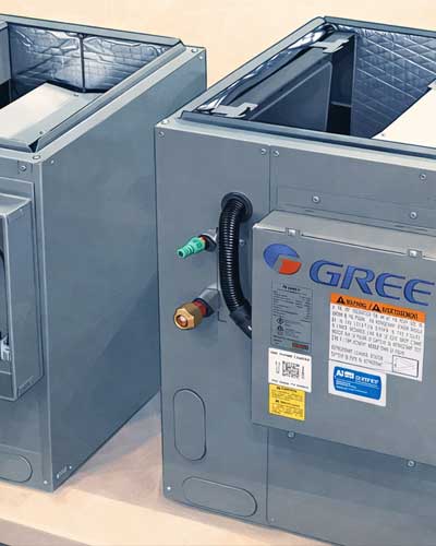
Applies to: GREE R32 Flex Air Handler series, R32 Flex Eco, 410A Eco Flex, and 410A Ultra models. The motor used in all three is the same.
What Do the Motor Wires Actually Do?
Each of the four motor wires in GREE FLEXX air handlers has a distinct diagnostic role:
| Wire Color | Function | When It Matters |
|---|---|---|
| Black | Common (ground reference) | All voltage tests use black as the reference |
| White | DC Power (15V) | Confirms the board is energizing the motor circuit |
| Yellow | PWM signal | Confirms the board is commanding the motor to start |
| Blue | Feedback voltage | Confirms the motor is actually running |
The blue (feedback) wire only becomes active once the motor is running. During initial diagnostics, focus on black, white, and yellow only.
How Do You Test Whether the Control Board Is Working?
The control board is confirmed working if it outputs 15V DC between black and white, and sends an increasing PWM signal on the yellow wire when a fan call is active.
To isolate the board from a potentially faulty motor:
- Disconnect the motor plug from the control board.
- Power the system back up and initiate a fan call.
- Set your multimeter to DC voltage.
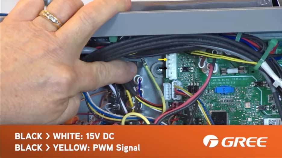
- Measure the pins as per the visuals below:
- Measure black (common) to white (DC power), you should read 15V DC.
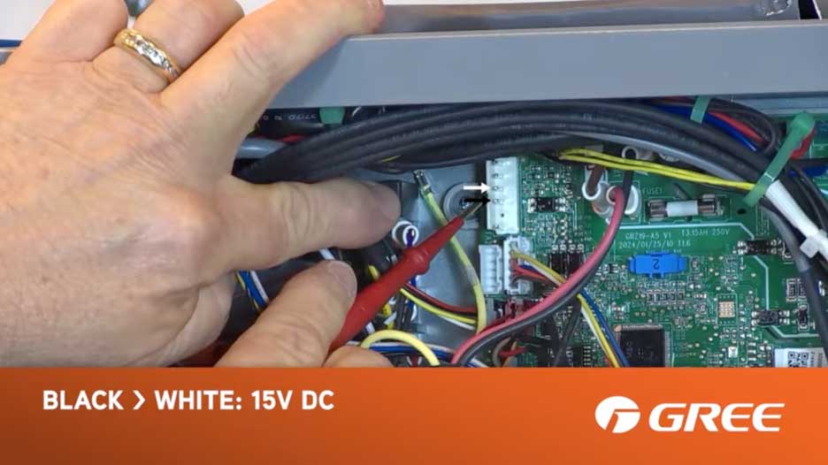
- Measure black (common) to yellow (PWM signal), you should see an increasing DC voltage signal.
If both readings are present, the board is functioning correctly. The problem is with the motor.
Watch the Full Tutorial Here:
What Does a Blinking Green Light Mean on a FLEXX Air Handler?
A blinking green light on the control board means the board has attempted to start the motor and received no feedback voltage on the blue wire. The green light may begin blinking before the board has fully locked out, it can retry on its own after a short pause. After approximately three total failed attempts, the board locks out completely and stops sending the PWM signal.
To reset the lockout: power down both the outdoor and indoor units and leave them off for at least 5 minutes before restarting, especially if H1 and H2 communication wires are connected between the indoor and outdoor units.
How Do You Test Whether the Motor Is Faulty?
Once the board is confirmed working, reconnect the motor and observe:
- Motor doesn't run despite receiving the PWM signal: The motor is faulty.
- Motor runs but never sends feedback voltage on the blue wire: The motor's internal module is defective.
Either condition indicates the motor needs replacement.
How to Bypass RS485 for Isolated Diagnostic Testing
If the indoor and outdoor units communicate via RS485 (H1/H2 wiring), you can isolate the air handler for standalone testing without needing the outdoor unit to issue a fan call.
Steps to bypass RS485 and simulate a fan call:
- Disconnect the H1 and H2 communication wires.
- Set dip switch SA1 to the ON position to enable 24-volt operation.
- Jump the R terminal to the G terminal to simulate a fan call signal.
If you are already using 24-volt control, verify that you are actually getting 24 volts to the G and C terminals before testing the motor circuit. A missing 24V supply will produce the same symptoms as a bad board.
When using RS485 control, make sure you are issuing a fresh fan call before testing. If the board has already locked out from a previous attempt, the PWM signal will not appear until the lockout is cleared. Power cycle the system, wait at least 5 minutes, then send a new fan call and begin testing immediately.
The diagnostic process is identical to the standard sequence above. This gives you an alternative way to run the same test, even if you're normally using RS485.
Frequently Asked Questions
What is the first thing to check on a GREE FLEXX Air Handler that won't turn on?
Start by testing the control board with the motor unplugged. Measure DC voltage between the black and white pins on the wiring harness, you should see 15V DC. Then check for a PWM signal between black and yellow. If both are present, the board is working and the motor is the likely culprit.
What does the yellow wire do on a GREE FLEXX air handler motor?
The yellow wire carries the PWM (Pulse Width Modulation) signal from the control board to the motor. It tells the motor to start. An increasing DC voltage on this wire when a fan call is active confirms the board is commanding the motor correctly.
What causes a blinking green light on a GREE FLEXX Air Handler control board?
A blinking green light means the board has attempted to start the motor and received no feedback voltage on the blue wire. The board may retry on its own after the green light starts blinking. After approximately three total failed attempts, it locks out completely. To clear the lockout, power down both units (if H1/H2 are connected) for at least 5 minutes.
How do I reset a GREE FLEXX Air Handler that is locked out?
Power down both the outdoor and indoor units completely and wait at least 5 minutes before restoring power, especially if H1 and H2 communication wires are connected between the indoor and outdoor units.
Which GREE air handler models use this same motor and wiring configuration?
The R32 Flex Air Handler series, R32 Flex Eco, 410A Eco Flex, and 410A Ultra, the motor used in all three is the same. The diagnostic steps in this guide apply to all of them.
What does the blue wire do on a GREE FLEXX air handler motor?
The blue wire sends feedback voltage from the motor back to the control board, confirming the motor is running. This signal only appears while the motor is in operation. If the motor runs but the board receives no feedback on the blue wire, the motor's internal module is considered defective.
How do I test a GREE FLEXX Air Handler without the outdoor unit connected?
Disconnect the H1 and H2 RS485 communication wires, set dip switch SA1 to ON for 24-volt operation, and jump the R terminal to G to simulate a fan call. This allows you to run the full board and motor diagnostic sequence without the outdoor unit present.