

What Is Dual Fuel and Why Does It Matter?
What Is Dual Fuel and Why Does It Matter?
A dual fuel HVAC system combines a heat pump and a gas furnace in one installation, both sharing the same blower and ductwork, and automatically uses whichever source is most efficient based on outdoor conditions. The heat pump handles heating and cooling during mild weather. When temperatures drop too low for the heat pump to operate efficiently, the gas furnace takes over.
The three core benefits are:
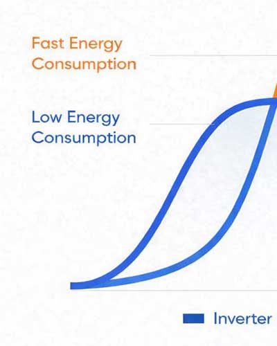
- Energy efficiency: The heat pump uses electricity more efficiently than gas during mild weather, reducing energy bills for the majority of the year.
- Cold-weather reliability: The gas furnace provides strong, reliable heat when outdoor temperatures reach extremes.
- Year-round comfort: One system handles both heating and cooling across all seasons, with both systems sharing the same blower and ductwork.
How cold can you go before needing the gas furnace?
With GREE Ultra models, the heat pump operates in heating mode down to -22°F, well below the old field rule of switching over at 35–40°F. In most dual fuel setups, the gas furnace is a backup rather than the primary cold-weather heating source.
The balance point, the outdoor temperature at which the gas furnace becomes more cost-effective than the heat pump, depends on the region, local utility rates, and whether the homeowner is burning natural gas or propane.
Key Features of the GREE Dual Fuel FXU Coil
The GREE FXU Coil is available in 2, 3, 4, and 5-ton sizes. The 4-ton and 5-ton units share a 24.5-inch-wide cabinet. All four sizes support four installation orientations and the unit ships from the factory configured for horizontal left and upflow. The R32 FXU coil also includes a built-in R32 leak detector for A2L refrigerant safety.
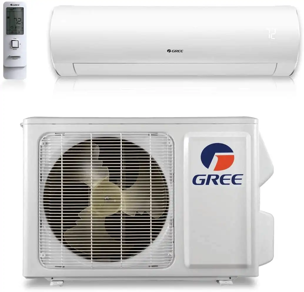
Which outdoor unit should you use: Flex Ultra or Flex Eco?
The choice depends on the installation region and the customer's budget. The operating ranges differ significantly:
An Eco unit can still be used in northern climates, the gas furnace provides backup for temperatures below 5°F. This makes the Eco a viable option when the customer's budget doesn't allow for the Ultra, while still delivering the dual fuel redundancy they need.
What diagnostic data does the RS485 controller provide in a dual fuel setup?
When H1 and H2 are connected to the outdoor unit, the RS485 controller displays compressor frequency, EEV step, and outdoor unit fan speed. Indoor fan speed is not available, the furnace is a separate manufacturer's equipment and does not communicate via H1/H2.
Connecting H1 and H2 is optional. However, even in 24-volt operation, the RS485 connection provides diagnostic data from the outdoor unit and indoor coil sensors, which is useful for commissioning and troubleshooting.
On R32 Flex units, connecting H1 and H2 also provides a performance benefit. The R32 FXU coil has inlet, outlet, and coil temperature sensors that feed data to the outdoor board through the H1/H2 connection. This gives the outdoor unit additional information to optimize compressor ramp rate beyond what the pressure transducer alone can provide. Without H1 and H2 connected, the system relies solely on the pressure transducer for ramp control, similar to how the 410A models operated.
Dual Fuel Step-by-Step Setup and Configuration
What do you need before starting a dual fuel installation?
Before beginning, confirm:
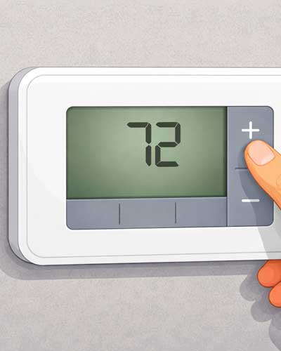
- A dual fuel heat pump thermostat is on hand, a standard thermostat will not work.
- The gas furnace can deliver 350–400 CFM per ton of airflow.
- An adjustable wrench and drill are available for orientation adjustments.
There is no transformer inside the FXU coil or the outdoor unit. The entire system runs on the 24-volt power supplied by the gas furnace transformer.
How do you set the dip switches for 24-volt dual fuel operation?
SA1 dip switch #1 must be set to the ON position on both the indoor coil control board and the outdoor unit. Always turn power off before moving dip switches.
The indoor coil control board also has two sensor dip switches, the air outlet temperature sensor and the freeze protection sensor, both factory-set to ON. Leave these in the factory position for standard dual fuel installations.
On the outdoor unit, SA1 dip switch #1 being ON tells the unit it is communicating with an A-coil rather than a traditional air handler. For SA1 switch #2, this setting informs the outdoor unit of the type of GREE indoor unit it's paired with. By default, it is set for a GREE air handler. If the switch is flipped, it changes the setting to recognize a GREE A-Coil. Adjusting this dip switch enhances communication between the indoor and outdoor units, allowing the outdoor unit to respond more quickly and operate more efficiently. While the system will still function without changing the setting, response times will be slower and overall efficiency may be reduced.
The outdoor unit is also compatible with third-party air handlers and A-coils. In those cases, there's no need to adjust SA1 switch #2, the default setting is sufficient. However, if you're using 24V communication instead of RS485, you will need to switch SA1 #1 to the ON position, as the default setting is OFF and configured for RS485.
How do you switch the RS485 controller to 24-volt mode?
This step is required for all dual fuel setups. The controller must be in Off mode before any installer settings can be changed.
- Set the controller to Off mode.
- Press Menu.
- Use the middle down arrow to scroll to Installer Setup. Press Set.
- Scroll down to RS485 (under Communication). Press Set, the value begins flashing.
- Use the up/down arrow to change from RS485 to 24 Volts.
- Press Set to confirm.
- Press Menu twice to return to the main screen.
With both SA1 dip switches set to ON, the controller in 24-volt mode, and a dual fuel thermostat connected, the system is ready to operate.
Why is a dual fuel thermostat required?
Running the heat pump and gas furnace simultaneously overheats the FXU coil. The coil sits directly above the gas furnace, when both run at once, the outlet temperature sensor detects the abnormal heat rise and the system opens the W circuit to protect equipment.
A dual fuel thermostat prevents this by shutting off the heat pump any time the gas furnace is called. This is a wiring and commissioning requirement, not an optional upgrade. Any brand of dual fuel thermostat will work, including the GREE controller, as long as it is configured for dual fuel operation.
For a single-stage gas furnace, the thermostat needs two stages of heat: Y for the heat pump and W2 for gas heat. For a two-stage gas furnace, three stages of heat are required: Y for the heat pump, W2 for first-stage gas, and W3 or AUX3 for second-stage gas. Only one stage of cooling is needed because the inverter-driven outdoor unit modulates capacity on its own.
How do you set operating mode and defrost mode?
These are configured via dip switches on the outdoor unit, with power off. Select the mode appropriate for the installation region.
Operating modes:
- Standard: factory default; suitable for most installations
- Strong: increases capacity output rapidly; for regions with extreme highs or lows
- Energy Saving: reduces load range to minimize energy consumption
- Self-Adaption: adjusts automatically to environmental conditions; available in 24-volt mode only
Defrost modes:
- Standard: factory default
- Snowy: for extreme cold regions such as North Dakota and Canada; triggers defrost more aggressively to complete it faster
- Humid Cooling: for high-humidity cooling climates
- Dry Cooling: for low-humidity cooling environments
In a dual fuel system, defrost has minimal impact on indoor comfort. The defrost cycle on these units lasts about two minutes, which is not long enough for the gas furnace ignition sequence to complete. By the time the furnace runs through its prep purge, inducer startup, igniter warmup, and fires the burner, the outdoor unit has already exited defrost. As a result, the system simply resumes heat pump operation without the furnace ever engaging during defrost.
How do you convert the FXU coil to horizontal right or downflow?
Horizontal right conversion:
The unit ships in horizontal left position. To convert:
- Remove the four cover screws and open the electrical compartment.
- Remove the coil mounting bracket screws and the top bracket screw.
- Remove the two screws on the downflow cover panel and set it aside (not needed for horizontal right).
- Slide the coil out of the housing.
- Flip the drain pan to the opposite side. Slide the coil back in.
- Move the control box to the pre-drilled holes on the other side.
The wiring harness is long enough to reach either side. When the box moves to the right side, flip the box cover so the labeling reads correctly.
Downflow conversion:
For downflow, swap the inlet and outlet temperature sensors, that is the only change required. In upflow position, the outlet sensor sits at the top and the inlet sensor at the bottom. Because airflow reverses in a downflow installation, these sensors must be physically moved.
To remove each sensor: loosen the retaining nut with an adjustable wrench and slide the sensor out. Both sensors are 20K thermistors. They cannot be reassigned on the control board, they must be physically swapped.
The coil must always be placed on the supply side, never the return. Installing on the return causes condensation to form on the heat exchanger and disrupts proper airflow velocity and static pressure.
How do you set blower speed and verify static pressure?
Regardless of furnace brand, target 350–400 CFM per ton of airflow. Pull the furnace's blower chart and configure the dip switches to reach this range.
One common issue: when the heat pump is running in heating mode, the blower must operate at full speed. Some furnaces only run the blower at 50% on a G-call alone. Confirm that the furnace delivers the full target CFM during a Y-call, not just during a G-call. If a variable speed blower is set for 1,200 CFM on a 3-ton system, that full 1,200 CFM must be reached while the heat pump is operating. The installing contractor is responsible for understanding the furnace's blower profile, since GREE does not control how other manufacturers' boards manage blower speed.
After setting blower speed, check total external static pressure with a manometer. Place the supply probe at the apex of the coil and the return probe pointing into the airstream, including the filter:
- Ideal: 0.3 inWC
- Maximum acceptable: 0.5 inWC
- Remediation required: 0.9 inWC or higher, add return vents, supply vents, or increase duct sizing
Insufficient airflow causes multiple problems. In heating mode, low airflow can trip H4 (compressor overload) because the inverter board is overloaded and compressor amperage runs too high. In cooling mode, the compressor slows itself down to prevent slugging, and if conditions persist, the outdoor unit enters a forced oil return cycle (fault code 09). Oil return looks similar to defrost but takes 4–5 minutes to complete instead of about 2 minutes, and repeated cycles reduce efficiency. Code 08 is defrost; code 09 is oil return. If 09 appears regularly, the cause is airflow, not refrigerant.
When the furnace and coil widths don't match, install a field-fabricated sheet metal transition. Mismatched widths without a transition restrict airflow through part of the coil, can cause partial freeze-up in cooling, and may overheat the furnace heat exchanger in heating.
Common Mistakes to Avoid with Dual Fuel Setups
- Not swapping sensors for a downflow conversion: If the inlet and outlet temperature sensors are left in the upflow position during a downflow installation, the board reads an artificially high temperature at the inlet and will either generate an E8 overheat fault or prevent the heat pump from running. The outdoor unit will not ramp up correctly and EEV adjustment will be erratic.
- Running the heat pump and gas furnace at the same time: Both systems running simultaneously overheats the coil and triggers a protection shutdown. A dual fuel thermostat is the required solution, not a field workaround.
- Incorrect static pressure: Low airflow from undersized ductwork causes oil return cycles and efficiency loss. Measure and confirm total static pressure is at or below 0.5 inWC before completing the installation.
- Skipping transitions on mismatched furnace and coil sizes: A sheet metal transition is required whenever the furnace outlet and coil widths differ, whether the coil is larger or smaller. Skipping the transition blocks airflow through part of the coil and can damage the furnace heat exchanger.
- Incorrect line set sizing: GREE specifies 3/8" x 3/4" refrigerant line sets for these systems. Using 7/8" suction line is not recommended. GREE does not provide a charging chart for non-standard sizes, and 7/8" line has produced audible vibration noise in the line set. Using 1-1/8" suction line is not acceptable and risks inadequate oil return and equipment damage.
- Directing UV lights at the EEV or coil wiring: Do not point UV lights at the electronic expansion valve or the coil wiring. UV exposure deteriorates the EEV stepper motor, and the coil wiring may not be rated for UV exposure.
Key Takeaways for Dual Fuel System Setups
- A dual fuel system pairs a heat pump and gas furnace sharing the same blower and ductwork, the FXU coil and outdoor unit have no transformer, using 24V from the furnace.
- The Flex Ultra operates down to -22°F; the Flex Eco operates down to 5°F. Select based on installation climate and customer budget.
- Set SA1 dip switch #1 to ON on both the indoor coil and outdoor unit (power off), then switch the RS485 controller to 24-volt mode via Installer Setup.
- H1 and H2 connections are optional but provide diagnostic data and, on R32 units, a performance benefit by feeding coil sensor data to the outdoor board for compressor ramp optimization.
- Never run the heat pump and gas furnace at the same time. A dual fuel thermostat is required.
- For downflow conversion, physically swap the inlet and outlet temperature sensors, both are 20K thermistors and cannot be reassigned on the board.
- Confirm the blower delivers full target CFM during a Y-call, not just during a G-call. Some furnaces only run the blower at 50% without a Y signal.
- Target 350–400 CFM per ton and 0.3 inWC static pressure. Fault code 09 = oil return; H4 = compressor overload; E8 = overheat protection; E2 = freeze protection.
- Always install the FXU coil on the supply side, not the return.
- MultiPRO dual fuel coils are in development but were not yet available as of this training (January 2026).
Frequently Asked Questions about GREE Dual Fuel Systems
What dip switches need to change for a GREE dual fuel setup?
Set SA1 dip switch #1 to ON on both the indoor FXU coil control board and the outdoor unit, with power off. Then switch the RS485 controller to 24-volt mode through the Installer Setup menu.
Is there a transformer in the GREE FXU Dual Fuel Coil?
No. Neither the FXU coil nor the outdoor unit contains a transformer. The system uses the 24-volt power supplied by the gas furnace transformer.
Do you have to connect H1 and H2 for dual fuel operation?
No. H1 and H2 are optional in a dual fuel setup. Connecting them allows the RS485 controller to display diagnostic data (compressor frequency, EEV step, and outdoor unit fan speed) but is not required for the system to operate. On R32 Flex units, connecting H1 and H2 also provides a performance benefit by feeding coil sensor data to the outdoor board for compressor ramp optimization.
What happens if you don't swap the sensors for a downflow conversion?
The board will read an abnormally high inlet temperature and will likely generate an E8 overheat fault or prevent the heat pump from running. The outdoor unit will not ramp up properly and EEV adjustment will be erratic.
Can the heat pump and gas furnace run at the same time?
No. Running both simultaneously overheats the FXU coil, causes pressure spikes, and triggers a protection shutdown. A dual fuel thermostat is required to interlock the two systems.
What static pressure is acceptable for the GREE FXU Coil?
Ideal static pressure is 0.3 inWC. The maximum acceptable is 0.5 inWC. At 0.9 inWC or higher, ductwork remediation is required.
What does fault code 09 mean on a GREE Flex system?
Code 09 indicates an oil return cycle, not a defrost cycle (code 08). Oil return is triggered by insufficient airflow and takes 4–5 minutes to complete. Repeated 09 codes indicate an airflow or ductwork problem.
What are the resistance values for the FXU coil temperature sensors?
Both the evaporator inlet and outlet pipe temperature sensors are 20K thermistors.
Does the gas furnace run during defrost?
No. The defrost cycle on these units lasts about two minutes, which is not long enough for the gas furnace ignition sequence to complete. The furnace cannot finish its prep purge, inducer startup, igniter warmup, and firing sequence before defrost ends, so the system simply returns to heat pump operation.
What thermostat brands work with a GREE dual fuel setup?
Any dual fuel thermostat will work, including the GREE controller, Honeywell, Ecobee, or White-Rodgers, as long as it is configured for dual fuel operation. The key requirement is that the thermostat interlocks the heat pump and gas furnace so they never run at the same time.
What does fault code H4 mean on a GREE FLEXX system?
H4 indicates a compressor overload. In a dual fuel setup, this is most commonly caused by insufficient airflow in heating mode. Low airflow overloads the inverter board and drives compressor amperage too high. Verify that ductwork and blower speed are delivering the target 350 to 400 CFM per ton.
Is the GREE Dual Fuel FXU Coil compatible with MultiPRO systems?
Not yet. Dual fuel MultiPRO coils are in development but were not available at the time of this training (January 2026).
Can a UV light be installed in the FXU coil area?
GREE advises against it. UV light deteriorates the EEV stepper motor, and the coil wiring may not be rated for UV exposure.