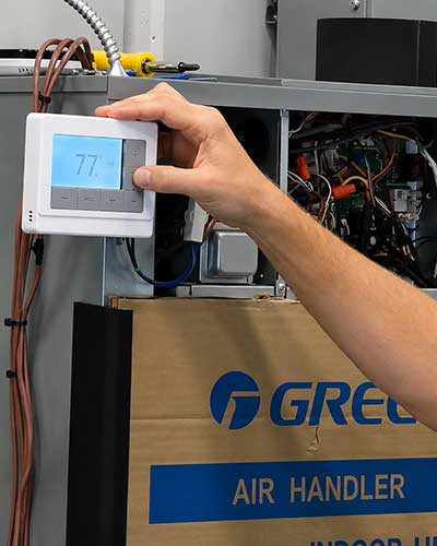


Proper Board Replacement for GREE Mini-Splits & FLEXX R32
In the HVAC world, precision and adherence to best practices are critical when it comes to system maintenance and repairs. One common challenge contractors face is the replacement of control boards in GREE Mini-Splits and FLEXX R32 systems. This task, though seemingly straightforward, requires attention to detail and adherence to specific procedures to avoid repeat failures and costly callbacks.
This article breaks down the essential steps, tools, and expert tips for performing a successful board replacement. Whether you're an experienced technician or new to the HVAC field, this guide will enhance your understanding and confidence when working on GREE systems.
Why Proper Board Replacement Matters with Mini-Splits & Central AC Systems
Replacing a control board is not just about swapping out an old component for a new one, it's about ensuring that the entire system functions optimally afterward. Improper board replacement can lead to issues such as repeat failures, damaged new boards, and prolonged system downtime for your clients. Doing the job right the first time prevents callbacks and ensures reliability. From critical thermal paste application to ensuring proper wire connections, every step plays a role in maintaining the system's performance and longevity.
Tools You'll Need For Board Replacement for Mini-Splits & Central Air
Before you begin, having the right tools on hand is essential for efficiency and accuracy. Here's a checklist of recommended tools:
- Screwdrivers: Both Phillips and flathead types, including a small thermostat screwdriver for precision tasks.
- Needle-nose pliers: For working with small components and tight spaces.
- Diagonal cutters (dikes): Useful for cutting zip ties and wires.
- Magnetic tray: To hold screws and avoid losing small parts.
- Gloves: Protects against messy thermal paste during application and cleanup.
- Digital multimeter: For checking voltage and confirming the board is safe to handle.
- Thermal paste: Included with new boards or purchased separately (ensure it's thermally conductive and compatible with electronics).
- Zip ties: For neatly securing wires after installation.
- Work surface: A portable, stable bench or table to simplify the process.
Step-by-Step Guide to Replacing Control Boards in GREE Mini-Splits
1. Safety First: Power Down and Discharge the Board
Turn off the power to the unit and wait for the board to dissipate stored energy. GREE boards can hold significant charge even after being powered off.
Use a multimeter to measure the DC voltage at the test points. Only proceed when the reading drops to 0 volts DC. If the DC test points are not accessible on your particular board, power the unit off and wait at least 10 minutes before handling any components.
Do not disconnect high-voltage loads (compressor, fan motor) before the DC bus has discharged. The compressor windings and fan motor windings serve as paths for the board to dissipate stored voltage. If you remove those loads while the capacitors are still charged, you have eliminated the board's ability to discharge itself, and the voltage will remain on the board longer.
Use the DC bus as a diagnostic tool, not just a safety check. If the DC bus voltage reads abnormally low, it can point directly to the problem. With the system powered up, unplug individual loads one at a time (e.g., condenser fan motor, then compressor) and see if the DC bus voltage comes back up. If unplugging the fan motor brings the bus back to normal, the fan motor was dragging it down. This narrows the diagnosis before ordering parts.
Check the Filter Board: On some older models (e.g., Multi-18 C revision units), a separate filter board sits between the incoming power and the main control board. If its fuse is blown, the main board will have no DC bus at all. Newer models integrate the filter board into the main inverter driver. When replacing a board on a system with a separate filter board, verify that the filter board is functioning. Replacing only the main board while the filter board has a blown fuse is a common oversight. To test the fuse, measure voltage across it. If you read voltage, the fuse is blown (it is dropping the voltage instead of passing it through). To determine whether the main board also needs replacement, bypass the blown fuse with alligator clips and a 5-amp fuse. If the system powers up and the condenser fan motor starts and the compressor begins its startup sequence, the main board is fine and only the filter board needs to be replaced.
Note for 115V units: On 115V boards, there are no labeled DC bus test points on the board itself. Instead, measure the DC bus voltage at the capacitor wires, specifically, the blue (ACN5) and brown (ACL4) wires where they connect to the board. The capacitors on 115V units are a separate part (the capacitor box assembly) wired to the board, and a failed capacitor on these units can produce an E6 error. If one of the capacitors has a blown-out or punctured white plug on top, that capacitor has failed.
2. Remove the Board from the Unit
Access the Control Box: Remove the unit's cover to expose the electrical components. Be methodical to avoid damaging sensitive parts. For units where the board is mounted vertically, remove the entire electric box assembly from the unit and work on it at a bench. Attempting to replace the board while it remains vertically installed makes it nearly impossible to properly access screws, increases the risk of dropping and losing hardware, and significantly raises the chance of an improper installation. Pulling the assembly takes less time than struggling to work in a confined vertical space.
Unplug Components: Disconnect all wires and plugs from the board, taking care to release their locking mechanisms. Some wires, such as compressor plugs, may require a small tool to release tabs securely.
Photograph Connections: Before removing wires, take clear photos of the board to use later as a reference for reconnecting components.
3. Detach the Board
Locate and remove all screws securing the board to the heat sink or mounting assembly. GREE boards often have recessed screws that must be fully tightened during reinstallation for optimal heat transfer.
Slide or lift the board out carefully, as it is often installed in tight spaces.
4. Inspect and Clean the Heat Sink
Remove Old Thermal Paste: Clean the heat sink thoroughly to eliminate debris, solder, or residue that could cause shorts or prevent effective heat transfer.
Apply New Thermal Paste: Use the thermal paste included with the new board. Place the old board and new board side by side, then apply paste to the same components on the new board that had paste on the old one. Apply the paste to the board's components, not to the heat sink. Use a modest amount and drag around the mounting holes, you do not want paste in the screw threads. Components with construction-paper-like insulation do not get paste.
Note for FLEXX R32 Units: The FLEXX R32 uses a cooling loop (a refrigerant pipe routed over the board) instead of a traditional aluminum heat sink to dissipate heat. Thermal paste is still applied beneath the cooling loop cover. The plastic housing surrounding the board stays in place, only the circuit board itself is removed during replacement.
5. Prepare the New Board
Transfer Jumper Caps: Many GREE boards use jumper caps (small, colored connectors) that must be moved from the old board to the new one. Ensure they are properly seated and match the original positions.
Set Dip Switches: Adjust the dip switches on the new board to match the settings of the old board or refer to the Quick Start Guide for appropriate configurations.
6. Install the New Board
Place the new board into the mounting assembly and align it with the heat sink.
Secure the board with screws, starting all of them before tightening any. Then work from the inner screws outward, snugging each one gradually in sequence, similar to torquing lug nuts. This ensures the board is pinched evenly against the heat sink for proper thermal contact. Do not use an impact driver, and do not over-tighten. The screws should be snug, not forced.
Reconnect all wiring and verify connections against your reference photos or the wiring diagram.
7. Test the System
Power on the unit and monitor for proper operation. Look for indicator lights or error codes that may signal issues.
Ensure the system runs without faults before reassembling the covers.
Common Pitfalls and How to Avoid Them
- Not checking for a grounded EEV before replacing a board: On the control board, the EEV connectors are labeled FA and FB. On the back side of the board near those connectors are small chips that will show a burnt spot if an EEV has shorted to ground. Before ordering a replacement board for an E6 error, ask for or take a close-up photo of the back of the board near FA and FB. If a burn mark is visible, the EEV needs to be replaced along with the board. Otherwise, the grounded EEV will destroy the new board on startup.
- Skipping the compressor plug check: When testing compressor windings, unplug the molex plug between the compressor and the board and ohm out the compressor from the plug toward the compressor, not from the plug toward the board. If the readings are abnormal (open winding or shorted to ground), go directly to the compressor terminals before condemning it. The issue may be in the wire harness between the plug and the compressor, not the compressor itself. There is also a small ferrite donut around the wires near the compressor, if the harness is damaged near it, the ohm reading from the molex plug will be misleading.
- Missing or Misaligned Screws: Improperly installed screws can cause insufficient heat dissipation, leading to board failure. Always ensure screws are fully tightened and aligned.
- Incorrect Wiring: Misplacing wires, especially on the compressor terminals (UV and W), can cause operational errors or damage.
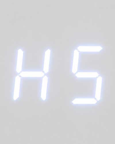
- Reversing the incoming power wires: On the board, the blue wire is ACN and the brown wire is ACL. These connect via stake-on terminals. If they are swapped during reassembly, the board will not communicate properly and may produce an H5 error code. The same applies to the filter board connections (N1, N2, and N3), reversing the blue and brown wires there will also break communication. Always photograph these connections before unplugging and verify wire placement against the wiring diagram.
- Skipping Thermal Paste: Forgetting to apply thermal paste or using the wrong type (e.g., heat sink paste used for brazing, which prevents heat transfer rather than conducting it) can lead to immediate board failure.
- Neglecting Jumper Caps: Missing jumper caps will prevent the system from functioning and result in error codes (e.g., C4 or C5 codes).
- Mixing R32 and R410A Parts: Boards and components from R410A systems are not compatible with R32 systems, and vice versa. Do not attempt to use parts from one refrigerant platform on the other, they likely will not fit, and even if they do, they will not function properly.
- Unnecessary Board Removal: Do not remove the board unless you intend to replace it. Pulling the board out disturbs the thermal paste, and reinstalling the same board without properly reapplying paste can create improper contact with the heat sink, potentially causing the very failure you were trying to prevent.
- Ignoring Voltage Hold: Attempting to handle the board before the DC voltage fully dissipates can result in injury or damage to components.
Key Takeaways
- Safety First: Always confirm DC voltage is at 0 before handling the board. Do not disconnect loads before the DC bus has discharged, the windings are what allow the board to dissipate stored voltage.
- Thermal Paste Is Critical: Apply conductive paste to the board's components (not the heat sink), clean the old paste off thoroughly, and avoid getting paste in screw threads. Use the old board as a reference for which components get paste.
- Jumper Caps Matter: Transfer jumper caps from the old board to the new one, ensuring they match the original layout.
- Photo Documentation: Take pictures of wiring connections before disconnecting to avoid errors during reinstallation. Pay particular attention to the blue (ACN) and brown (ACL) incoming power wires, reversing them causes H5 errors.
- Step-by-Step Torquing: Start all screws before tightening any, then snug them from the inner screws outward, like torquing lug nuts, for proper board-to-heat-sink contact.
- DC Bus as Diagnostic: A low DC bus reading can identify a dragging fan motor or grounded compressor without ordering parts. Unplug loads one at a time and monitor the bus voltage.
- Check for Grounded EEVs: Before replacing a board for an E6 error, inspect the back of the board near the FA/FB connectors for burnt chips. A grounded EEV will destroy the new board.
- Filter Board and 115V Differences: On models with a separate filter board, a blown fuse there eliminates all DC bus power. On 115V units, there are no DC bus test points on the board, test at the capacitor wires (ACN5/ACL4) instead.
- Check Dip Switch Settings: Verify all dip switches are configured correctly for the system's capacity and operation mode.
- Use Reliable Tools: A magnetic tray, gloves, and multimeter are non-negotiable for efficiency and safety.
Replacing a control board in GREE Mini-Splits or FLEXX R32 systems requires precision and attention to detail. By following the outlined steps and avoiding common mistakes, you can ensure a successful replacement that minimizes downtime and maximizes client satisfaction. With the growing popularity of inverter-driven systems, mastering these skills will keep you ahead in the competitive HVAC industry.
Stay diligent, follow procedures, and remember: the right tools and knowledge make all the difference in delivering reliable, high-quality service.