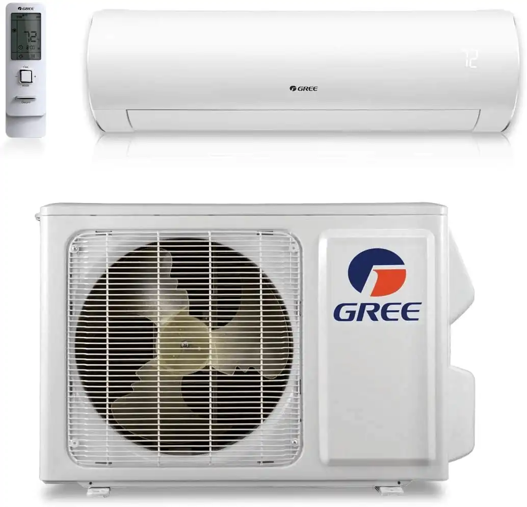


How Do You Install a GREE MultiPRO R32 System? Selection Software, Piping, Wiring, and Startup
| A field guide for HVAC contractors installing the GREE MultiPRO R32 (GMV6 Ultra) light commercial/residential system: how it differs from a mini-split, how to size it in the selection software, the Y-branch and header piping rules, wiring and controls, evacuation and charging, and the on-board startup and debug sequence. |
TL;DR: MultiPRO R32 Installation Essential Tips
The GREE MultiPRO R32 is a mini-VRF system, not a multi-zone mini-split: the electronic expansion valve is in each indoor unit. Indoor units connect through Y-branches or headers, never separate line sets. Size systems in the R-32 selection software by BTU capacity. A 3-ton supports up to 7 indoor units, a 4-ton supports 8, and a 5-ton supports up to 10. However, they can also be used in a 1 to 1 application. Keep each run under 50 feet from the Y-branch or header. Evacuate from both sides with service valves closed, charge before powering indoor units, give the compressor its crankcase warmup, then run the on-board debug. See the MultiPRO R32 product line.
What Is the GREE MultiPRO R32 and How Is It Different From a Mini-Split?
The GREE MultiPRO R32 is a mini-VRF system, not a multi-zone mini-split. On a multi-zone mini-split the electronic expansion valve (EEV) is in the outdoor unit; with the MultiPRO R32 the EEV is located in each indoor unit. That single difference drives every piping and startup rule in this guide.
Because the metering happens at the indoor unit, the system feeds a solid column of liquid to each indoor coil in cooling and hot gas to each coil in heating. You don’t have to run multiple individual line sets to the outdoor unit the way you would on a multi-zone mini-split. Indoor units connect through Y-branches or headers instead.
The R-32 lineup currently covers the 3-ton, 4-ton, and 5-ton outdoor units (the first batch is the Ultra series), with 24K and 28K sizes expected in the future. When servicing a system, contractors must also maintain a 50% connected capacity ratio: on a 4-ton system running two 2-ton indoor units, one 2-ton unit can stay running while the other is shut down.
How Many Indoor Units Can a MultiPRO R32 Support?
A 3-ton MultiPRO R32 supports up to 7 indoor units, a 4-ton supports up to 8, and a 5-ton supports up to 10. All R-32 indoor units from 5,000 to 12,000 BTU now share the same standard port sizes, which simplifies selection and piping.
Indoor capacity is selectable on most units by setting dip switches, so you order one unit and adjust it to multiple capacities. Always set the dip switches with the power off. The dip-switch capacity chart for each unit is on the GREE commercial website under the R-32 indoor units. You can find the full MultiPRO R32 indoor unit capacity chart here.
| Ordered indoor unit | Selectable capacities (via dip switch) |
|---|---|
| 9K (high wall and most types) | Adjustable down to 6K or 7K |
| 12K | Adjustable up to 14K |
| 24K | Adjustable down to 18K (an 18K can be set to 12K) |
| Compact ceiling cassette | Only unit that can be set as low as 5,000 BTU |
| 2-ton standard cassette | Capacity not adjustable |
The current MultiPRO R32 quick reference guide shows which units are adjustable (the capacities in bold are the ones you order). The compatible indoor unit types in this first iteration are the high wall (wall mounted), the compact ceiling cassette, the standard one-way ceiling cassette, the slim ducted, and the air handlers.
What Are the MultiPRO R32 Piping Rules for Y-Branches and Headers?
The MultiPRO R32 uses the same Y-branch and header rules as the R-410A commercial product. The basic rules let you lay out a job without a computer; anything outside them must be run through the selection software so it can verify the line sizes. Try to maintain at least 10 feet of refrigerant line length between the outdoor unit and the first Y or header. This allows the refrigerant to be balanced before being distributed.
How Do You Select a MultiPRO R32 System in the Selection Software?
Open the MultiPRO R32 quick reference guide. It lists every indoor unit, the capacity charts, and the accessory options you will select from. As you’re selecting your units, remember that MultiPRO R32 systems must have a connection ratio of 50-135%. To calculate this, take your indoor unit BTUs, divided by your outdoor unit BTU, this gives your connection capacity ratio.
Once you’re ready, use the GMV selection software version 2.5.20, the version that contains the R-32 products. The software is Windows only and does not run on a Mac/Apple computer.
Download the software from GREE’s commercial website using the GMV selection software link at the top of the page, then fill out the four request boxes and submit to receive the file. On first launch, change the first dropdown from Europe to North America, then scroll to the bottom of the unit list, because the R-32 products sit below the R-410A commercial products.
Select Indoor Units by BTU Capacity, Not by Model
Select indoor units by BTU capacity, because the R-32 selection software is still in testing and does not yet include every indoor unit. If the exact model you want is missing (for example a specific wall mount), pick another indoor unit of the same BTU capacity, such as the compact ceiling cassette. The line-set sizing is driven by BTU capacity, not by indoor-unit type, so the piping and charge results stay correct. You can enter the height difference between the outdoor and indoor units, which the software adds to the piping distance for a more accurate refrigerant charge.
Pipe sizes change in the real world once a job is as-built, so save each layout (it can be reused as a template or per-job file) and redo the selection after the actual pipe sizes are known. The software then produces a report with a bill of materials, the Y-branches and reducers, the total piping footage, and a piping layout you can hand to the installing technician.
Y-Branch Orientation: Level, Up, or Down
Y-branches can be installed vertical up, vertical down, or 100% level horizontal. The way to picture it: if the Y-branch were set on a level table it would sit flat, and that is how it must be installed even when hanging in the air, with both the liquid and gas pipes level. If a Y-branch is piped upright incorrectly, the liquid refrigerant pools, you get bubbles, and the expansion valve is not fed properly.
Header Orientation: Horizontal Only
Headers must be installed 100% level and horizontal, never vertical up or down. The gas header is turned so the gas lines run straight out, not up, and the liquid header has its elbow pointing down and then straight out. The two are designed to stack, with the gas pipe in front of the liquid pipe. A header turned up will not feed the system correctly.
Maintain at least 20 inches between any two Y-branches or header connections, and at least 20 inches off a Y-branch or header before any 90-degree bend. The presenters use a rule of thumb of about three feet, which guarantees the 20-inch clearance.
The 50-Foot Rule and Pipe Up-Sizing
Keep every indoor unit within 50 feet of its Y-branch or header. Beyond 50 feet the selection software up-sizes the pipe, which forces you to reduce back down at the indoor unit to match the connection flares, making the install harder. The maximum suction line size is 5/8 inch.
Sometimes when using the selection software, when the run exceeds 50 feet it up-sizes the liquid line but does not automatically up-size the gas pipe. Whenever the liquid line is up-sized one size, up-size the gas pipe one size as well. The practical fix is to move Y-branches closer to the indoor units so every run stays under 50 feet and the pipe size matches the connection size. If a header cannot be laid out under 50 feet, use multiple Y-branches instead, which can be repositioned, but multiple Y-branches must be calculated in the selection software rather than by basic rules.
Can You Use Press-Fit Fittings on a Y-Branch?
You cannot press-fit directly onto a Y-branch, because the ends are graduated and swedged to the size of the pipe they connect to and are designed to be brazed. To use press fittings, bench-set the Y-branch, flow nitrogen through it, and braze copper stubs onto each end first (for example an 8-inch stub and a 5-inch stub so the press fittings clear each other), then press onto the stubs. The same applies to the gas pipe.
How Do You Wire a MultiPRO R32 System?
Wire the MultiPRO R32 differently from a mini-split: bring high voltage to the outdoor unit, and run separate line voltage to each indoor unit (indoor units are not powered from the outdoor unit the way a mini-split is). The communication wire between units is 18/2 stranded wire, and it includes the terminating resistor that the wiring diagram calls out.
Each indoor unit needs a means of disconnect. For a simple indoor unit with no heat kit (a pancake ducted unit, cassette, or wall mount) a two-pole toggle switch works, because these are 230-volt or 208-volt indoor units and you need to kill both legs of power. A unit with a heat kit needs a disconnect rated for the added amp draw, and for a large heat kit (such as 20 kW) it may make more sense to switch the breaker. When indoor units have individual electrical disconnect switches, the power can be turned off to one unit for servicing and the other units will continue to run, provided you maintain 50% connected capacity.
Control Options and 24-Volt Adapters
Ductless units come with a standard wireless remote. Ducted units will all come with the XE7C-23H wired controller. Optional indoor unit controls include the XE7C-23H, ME32-23H, and the ME32-33H. Optional system controls include Cool Automation or Central Control. Refer to the quick reference guide for the full selection.
For a third-party 24-volt thermostat, use a 24-volt adapter, which converts the thermostat’s 24-volt input into CAN-bus communication to the unit. The ME32-23H is a two heat, one cool adapter with an OB terminal, so it can drive a heat pump as first-stage heat and a boiler or hot water (radiant) heat as second stage. The ME32-33H is a one heat, one cool adapter. To keep backup heat fully independent, add a relay that breaks Y to the outdoor unit when the backup heat is energized so the heat pump does not run.
| 24V adapter | Stages | Notes |
|---|---|---|
| ME32-23H | Two heat / one cool | Has an OB terminal; can run heat pump plus hot water or radiant backup heat; converts 24V to CAN bus |
| ME32-33H | One heat / one cool | Y energizes cooling, W energizes heating |
Wiring a Condensate Float on a Wall Mount
The new wall mounts shipped without the jumper and float connection that the R-410A units had (GREE is revising this in the future). Until it returns, power the condensate pump from L1 and L2, and break either D1 or D2 (the communication wire) with the pump float. Breaking communication is the only reliable method here, not a preferred one. If you broke line voltage instead, a float trip during cooling would leave the indoor EEV powered open while the blower stops, freezing the coil. Breaking communication closes the EEV and throws a communication code, which safely shuts it down.
On the new wall mounts, you no longer cut the molex plug to connect a wired controller. A pigtail adapter is included in the bag with the unit: plug it into the molex plug and wire-nut it to H1 and H2.
How Do You Evacuate and Charge a MultiPRO R32 Before Startup?
Do not apply power to the indoor units until you have completely evacuated the system and added the required additional charge, because powering the indoor units drives the electronic expansion valves closed. With the EEVs factory-open, refrigerant can flow all the way through to the low side while the system is still in vacuum.
Pull the vacuum from both the high and low sides with the outdoor service valves kept closed. Pressure-test the system, then triple-evacuate it. With everything in vacuum, weigh in the additional charge determined by the selection software through the liquid (high) side with the tank inverted; it flows through the factory-open indoor EEVs and back to the low side before you ever open the service valves.
Only after the additional charge is in should you power the indoor units. If you ever try to add refrigerant with the EEV valves closed and it will not flow, someone has already powered the indoor units and closed the EEVs.
How Do You Start Up and Debug a MultiPRO R32?
Before startup, give the compressor its crankcase warmup so there is no liquid refrigerant in it: power must be applied to the outdoor unit for a minimum time based on the outdoor temperature. The entire system charge sits in the outdoor unit, so in cold weather liquid refrigerant can collect with the cold oil and damage the compressor on start.
| Outdoor temperature | Minimum warmup before startup |
|---|---|
| Above 50 F | 1 hour |
| 32 F to 50 F | 2 hours |
| 14 F to 32 F | 4 hours |
| Below 14 F | 8 hours (full warmup) |
Powering the unit while you do the refrigerant piping counts toward the warmup. A brief power-down of 20 to 30 minutes to make the final permanent connection does not reset the 8-hour board timer, but leaving it off for hours does, so you would start the warmup over.
Confirm AO Before You Debug
With everything powered up, every indoor unit, its controller, and the outdoor unit should display AO. If a unit shows CO, it is not communicating with the outdoor unit: check that it has power and that the communication wires are connected correctly. Walk the building and confirm AO on every unit before proceeding to startup.
Running the On-Board Debug Sequence
Start the debug by pressing and holding SW3 for five seconds. The board has four buttons (SW1 through SW4), and all of the debug step descriptions are printed on a sticker on the bottom service panel door. The system self-addresses and runs through the steps automatically; a new installation should run the full debug, and any fault throws an error code that stops the process.
| Step code | What it means |
|---|---|
| Enter debug | Press and hold SW3 for 5 seconds |
| 02 | Self-addressing of units |
| 03 | Displays the number of outdoor units (for example 03 / 01 = one outdoor unit) |
| 07 | Error Code Check |
| 08 UO | Warmup not yet met; if the warmup rules were followed, press SW3 once to move on |
| 10 | Judgment of outdoor valves before startup (service-valve check) plus a ~2-minute compressor run |
| 12 (12 AP / 1201) | Brief pause in case additional refrigerant needs to be added while the unit is commissioning. This gives time to set up before finishing commission. |
| 15 AC | Runs ~50 minutes in cooling (AC); add additional charge during this run if needed |
| 16 AH | Forced to start in heating (AH) due to outdoor temperature; cannot add charge (both sides high pressure) |
If the system starts in 16 AH (heating mode) because of a low outdoor temperature, let it finish its roughly 50-minute run on the factory base charge, then switch all indoor units to cooling, add the additional charge, and set it back to heating. Around 50 degrees outside, an outdoor-mounted unit will most likely start in heating.
For a system that has already been commissioned (for example after adding a unit), you do not have to run the full debug. Once it gets past step 02 addressing and reaches step 03, press and hold SW2 and SW3 (buttons 2 and 3) for 10 seconds to bypass the rest of the debug. Pressing 2 and 3 also exits debug. Adding a unit requires re-addressing the machine so it recognizes the new indoor unit.
For additional instructions, watch the full MultiPRO R32 overview video:
Frequently Asked Questions
Is the GREE MultiPRO R32 a multi-zone mini-split?
No. The GREE MultiPRO R32 is a mini-VRF system. On a multi-zone mini-split the electronic expansion valve (EEV) is in the outdoor unit, while on the MultiPRO R32 the EEV is located in each indoor unit. Indoor units connect through Y-branches or headers, never separate line sets.
How many indoor units can a MultiPRO R32 outdoor unit support?
A 3-ton MultiPRO R32 supports up to 7 indoor units, a 4-ton supports up to 8, and a 5-ton supports up to 10. The systems can also be used in a 1 to 1 application.
What connection ratio does a MultiPRO R32 system require?
MultiPRO R32 systems must have a connection ratio of 50-135%. To calculate it, take your indoor unit BTUs divided by your outdoor unit BTU. When servicing, maintain a 50% connected capacity ratio: on a 4-ton system running two 2-ton indoor units, one 2-ton unit can stay running while the other is shut down.
What software do you use to select a MultiPRO R32 system?
Use GMV selection software version 2.5.20, the version that contains the R-32 products. The software is Windows only and does not run on a Mac/Apple computer. On first launch, change the first dropdown from Europe to North America, then scroll to the bottom of the unit list, because the R-32 products sit below the R-410A commercial products.
How must MultiPRO R32 Y-branches and headers be oriented?
Y-branches can be installed vertical up, vertical down, or 100% level horizontal. Headers must be installed 100% level and horizontal, never vertical up or down. Maintain at least 20 inches between any two Y-branches or header connections, and at least 20 inches off a Y-branch or header before any 90-degree bend.
How far can an indoor unit be from its Y-branch or header?
Keep every indoor unit within 50 feet of its Y-branch or header. Beyond 50 feet the selection software up-sizes the pipe, which forces you to reduce back down at the indoor unit to match the connection flares. The maximum suction line size is 5/8 inch. Sometimes when the run exceeds 50 feet the selection software up-sizes the liquid line but does not automatically up-size the gas pipe, so whenever the liquid line is up-sized one size, up-size the gas pipe one size as well.
Can you use press-fit fittings on a MultiPRO R32 Y-branch?
Not directly. Y-branch ends are graduated and swedged to the size of the pipe they connect to and are designed to be brazed. To use press fittings, bench-set the Y-branch, flow nitrogen through it, braze copper stubs onto each end, then press onto the stubs.
Why do you charge a MultiPRO R32 before powering the indoor units?
Powering the indoor units drives the electronic expansion valves closed. With the EEVs factory-open, the additional charge determined by the selection software, weighed in through the liquid (high) side with the tank inverted, flows through to the low side while the system is still in vacuum, before the service valves are opened. If refrigerant will not flow when you try to add it, someone has already powered the indoor units and closed the EEVs.
How long must the compressor warm up before startup?
Power must be applied to the outdoor unit for a minimum time based on outdoor temperature: 1 hour above 50 F, 2 hours from 32 F to 50 F, 4 hours from 14 F to 32 F, and 8 hours below 14 F. Powering the unit while you do the refrigerant piping counts toward the warmup. A brief 20 to 30 minute power-down does not reset the 8-hour board timer, but leaving it off for hours does, so you would start the warmup over.
What does it mean if a MultiPRO R32 indoor unit displays CO instead of AO?
A unit showing CO is not communicating with the outdoor unit. Check that it has power and that the communication wires are connected correctly. Every indoor unit, its controller, and the outdoor unit should display AO before you proceed to startup.